Electronic Enclosure & Injection Mold Design Case Study
Production Electronic Housing from Product Design Through Injection Mold Tooling
Client: Romulus Energy
An electronic enclosure must do much more than create an attractive outer shell.
It must package the electronics correctly, position interfaces accurately, support assembly, protect internal components and be designed around the intended manufacturing process.
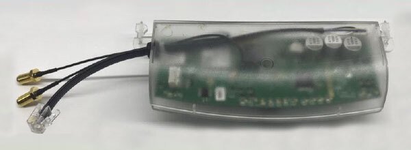
For the Romulus Energy AS1X Modem Meter, Ben Nel developed the production electronic housing and also designed the complete injection mold tooling used to manufacture the enclosure components.
The product entered commercial production in approximately 2018, with production exceeding:
5,000 Units
This project demonstrates experience spanning:
electronic enclosure design
aesthetic product development
internal component packaging
injection molding DFM
production-ready CAD
injection mold tooling design
transition from product geometry to production manufacture
[IMAGE: Best AS1X enclosure render]
Project at a Glance
Client: Romulus Energy
Product: AS1X Modem Meter
Product type: Electronic / electrical communications product
Production: Approximately 2018 onward
Production quantity: More than 5,000 units
Primary manufacturing process: Injection molding
3DDFM / Ben Nel role: Product design, aesthetic development, electronic enclosure engineering, internal component packaging, injection molding DFM and complete injection mold tool design
Production status: Commercially manufactured product
The Electronic Enclosure Challenge
Electronic product development requires several systems to fit together inside a limited physical envelope.
The enclosure must accommodate the electronics while also satisfying:
user-interface requirements
connector positions
PCB location
component clearances
fastening
assembly
structural requirements
external appearance
injection molding constraints
This creates an important design relationship:
Electronics → Internal Architecture → Enclosure Geometry → Tooling → Assembly → Production
If these areas are developed independently, problems are often discovered late.
For example:
connectors may not align correctly with enclosure openings
internal components may interfere with ribs or bosses
the PCB may be difficult to install
fastening features may cause molding defects
cosmetic surfaces may be affected by internal geometry
assembly access may be poor
product geometry may create unnecessary tooling complexity
The enclosure therefore needs to be engineered as part of the complete product rather than treated as packaging added after the electronics are complete.
Electronic Enclosure Design
The AS1X project required the external product and internal mechanical architecture to work together.
Ben’s enclosure-development work included:
overall product form
aesthetic design
enclosure architecture
internal component packaging
PCB and electronics accommodation
mounting and locating features
production-part geometry
enclosure split and assembly considerations
injection molding DFM
The objective was to develop a housing that satisfied both the electronic-product requirements and the manufacturing process.
romulus as1x electronic enclosure design
Designing Around the Electronics
One of the most important parts of electronic enclosure engineering is establishing the relationship between the enclosure and the internal components.
The mechanical design may need to accommodate:
PCBs
connectors
switches
LEDs
displays
wiring
terminals
mounting hardware
other electrical components
These elements influence the enclosure’s:
overall size
wall positions
internal ribs
bosses
openings
mounting points
assembly direction
part separation
Poor internal packaging can result in an enclosure that becomes unnecessarily large or difficult to assemble.
The internal architecture must therefore be developed together with the external product geometry.
Injection Molding DFM
Because the production housing was intended for injection molding, the enclosure components had to be developed around molding requirements rather than simply around appearance.
Important considerations included:
controlled wall thickness
draft
ribs
bosses
internal support features
parting strategy
manufacturable internal geometry
assembly features
cosmetic surfaces
tooling access
Electronic enclosures often contain many internal ribs, bosses and mounting features.
These features are useful mechanically, but poor geometry can cause manufacturing problems including:
sink marks
warpage
difficult ejection
unnecessary tooling complexity
visible cosmetic defects
This means the mechanical requirements of the electronics must be balanced against the realities of injection molding.
For detailed injection molding principles, see:
Injection Molding Design Guidelines
From Product Design into Injection Mold Tooling
A significant part of this project was that Ben’s involvement did not end with the product CAD.
For the AS1X enclosure, Ben designed the complete injection mold tooling for the molded enclosure components.
This required translating the production part geometry into a tool capable of manufacturing the parts repeatedly.
This experience provides a practical connection between:
Product Geometry → DFM → Mold Construction → Molded Part
Understanding this relationship is valuable during product design because features that appear simple in CAD can create significant tooling consequences.
Examples include:
undercuts
parting geometry
shut-offs
deep features
ejection requirements
thin steel conditions
internal bosses and ribs
cosmetic parting lines
The AS1X project therefore provides direct experience on both sides of the tooling interface: designing the product and designing the mold used to produce it.
Why Tooling Knowledge Matters During Enclosure Design
An enclosure designer does not need to design the mold on every project.
However, understanding mold construction improves DFM decisions before the CAD is released to a toolmaker.
For example, tooling knowledge helps identify whether a product feature may require:
a slider
a lifter
a more complex parting line
additional inserts
difficult ejection
thin or weak steel conditions
unnecessary mold complexity
Sometimes a relatively small product-design change can simplify the production tool substantially without changing the intended product function.
This is one reason tooling considerations should begin during product design rather than only after the product is sent for quotation.
Production-Ready CAD Is More Than a Finished 3D Model
A visually complete enclosure is not necessarily ready for production.
Production-ready enclosure development requires consideration of:
manufacturable geometry
assembly
component fit
tolerances
fastening
tooling
cosmetic surfaces
manufacturing variation
The mechanical design must remain practical when real parts are molded and real electronics are assembled.
For companies developing PCB-based products, the transition from prototype enclosure to production housing is often one of the most important stages of the development process.
A 3D-printed enclosure may prove the size, appearance and basic function of a product, but production injection molding introduces a different set of engineering constraints.
Prototype Enclosure vs Production Enclosure
A prototype enclosure may be optimized for:
rapid manufacture
easy design changes
simple assembly
low quantities
A production injection molded enclosure must also account for:
tooling
draft
wall thickness
ejection
shrinkage
molding variation
cycle repeatability
production assembly
unit volume
Therefore, a prototype should not automatically be sent to an injection mold manufacturer without reviewing whether the geometry is appropriate for production.
This transition is a core part of:
What Does This Case Study Demonstrate?
Have you designed electronic enclosures that reached commercial production?
Yes.
The Romulus AS1X was developed as a production electronic product, with more than 5,000 units manufactured.
The work included product design, electronic enclosure development, internal component packaging and injection molding DFM.
Can you design a housing around a PCB and electronic components?
Yes.
Electronic enclosure development requires the internal components, mounting features, interfaces, fastening strategy and enclosure geometry to be developed as a complete system.
3DDFM’s Electronic Enclosure Design service focuses on this integration.
Electronic Enclosure Design Service
Do you have injection mold design experience?
Yes.
For the AS1X project, Ben Nel designed the complete injection mold tooling for the production enclosure.
This case study is evidence of that tooling experience.
Our current core service offering remains focused on product design, DFM and preparing products correctly for manufacturing.
Why is injection mold experience useful when designing plastic products?
Because the geometry of the product directly affects the complexity of the production tool.
Understanding tooling helps identify risks such as:
undercuts
difficult parting conditions
ejection problems
thin steel
difficult shut-offs
unnecessary tool actions
This can help improve product geometry before tooling begins.
For products preparing for injection molding, see:
Injection Molding Design Service
Can a 3D-printed electronic enclosure be converted to injection molding?
Often yes, but it should normally be redesigned or reviewed before production tooling is ordered.
Prototype geometry may contain:
excessive wall thickness
insufficient draft
unsupported bosses
geometry that cannot be molded
fastening methods that do not scale well
unrealistic tolerances
The production version should be engineered around the intended molding and assembly process.
Should the PCB or enclosure be designed first?
Ideally, they should be developed with continuous coordination between the electronics and mechanical design.
Critical electronic interfaces such as:
PCB dimensions
connector positions
display positions
buttons
LEDs
batteries
should be defined early.
The enclosure can then be developed around those constraints while allowing feedback between the electronics and mechanical design as the product evolves.
When should an electronic enclosure receive a DFM review?
Before significant money is committed to production tooling.
A DFM review can identify problems involving:
molding
internal component layout
assembly
tolerances
fastening
tooling complexity
production feasibility
If your enclosure CAD already exists and you want it independently reviewed before tooling, see:
Design for Manufacturing Consulting
Electronic Enclosure Design Principles
Electronic enclosures require a balance between the internal electronics, user interfaces, mechanical requirements and manufacturing process.
Important areas include:
PCB mounting
component clearance
fastening
connector alignment
wall thickness
ribs and bosses
sealing where required
assembly sequence
production method
For a detailed technical overview, see:
Electronic Enclosure Design Guide
The AS1X case study demonstrates how these principles can be applied to a real commercial electronic product that progressed into injection molded production.
Need an Electronic Enclosure Prepared for Production?
3DDFM supports companies developing PCB-based and electronic products that need production-ready mechanical housings.
Our work can include:
enclosure architecture
PCB and component packaging
aesthetic product design
fastening strategy
Design for Assembly
injection molding DFM
production-ready CAD
toolmaker interaction
manufacturing review
Electronic Enclosure Design Service
Design for Manufacturing Consulting
More Production-Proven Engineering Case Studies
See additional manufacturing examples covering high-volume injection molded electrical products and production sheet metal engineering.
View Manufacturing Case Studies