Snap-Fit Design Calculator (Injection Molding DFM Tool)
Introduction
Use this snap-fit calculator to quickly evaluate cantilever snap-fit designs for injection molding. Enter your dimensions and material to check strain, assembly force, and potential failure risks before tooling.
🔲 Quick Design Rules
- Keep L/h > 10
- Use generous root radius (R ≥ 0.4h)
- Prefer tapered arms
- Reduce deflection for stiff materials
- Avoid repeated use with brittle plastics
🧮 Calculator Section
Snap-Fit Design Calculator for Injection Molding
First-pass cantilever snap-fit screening for thermoplastic parts. Check strain risk, assembly force, retention behavior, and practical DFM improvements.
Assessment
Why this result?
Suggested improvements
If your snap-fit is borderline or high risk, request a detailed design review before tooling. This helps catch cracking risk, assembly force issues, warpage sensitivity, and manufacturing constraints earlier.
Want a professional review of your actual CAD? Get a fixed-fee DFM review.
 Want to know how much the injection mold tooling and production will cost?
 Check Injection Mold Cost Estimator
Not sure which material to use?
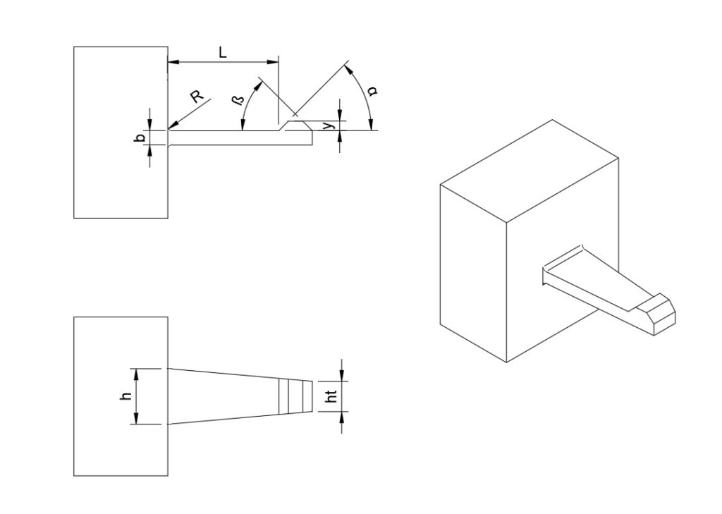
📐 Diagram Section
🔧 Engineering Explanation
Snap-fit joints work by temporarily deforming a flexible feature (the cantilever arm) so that it can pass over a mating feature and then return to its original shape to lock in place.
The key engineering principle behind this is strain control.
1. What happens during assembly
When the parts are pushed together:
- The snap arm bends outward
- The outer surface of the arm goes into tension
- The inner surface goes into compression
- The highest stress occurs at the root of the arm
Once the hook clears the mating feature, the arm springs back, creating the locking action.
2. Why snap-fits fail
Snap-fits typically fail for one of three reasons:
- Excessive strain → material cracks or permanently deforms
- High assembly force → difficult or impossible to assemble
- Poor geometry → stress concentration at the root
The most critical factor is strain at the outer fiber of the arm.
If this exceeds what the material can handle, failure is very likely.
3. Why arm length is critical
The ratio of length to thickness (L/h) determines flexibility.
- Long, thin arms → flex easily, lower strain
- Short, thick arms → very stiff, high strain
This is why increasing arm length is often the most effective fix.
4. Why root radius matters
The base of the snap arm is the highest stress location.
- Sharp corners → concentrate stress → cracking risk
- Larger radii → distribute stress → improved durability
A small radius is one of the most common causes of failure in real parts.
5. Material behavior
Different plastics behave very differently:
- Ductile materials (PP, PE, POM) → can handle larger deflection
- Brittle materials (ABS, filled plastics) → fail at lower strain
For repeated use, allowable strain is significantly lower.
A design that works once may fail after a few cycles.
6. Assembly force and usability
Even if a snap-fit survives structurally, it may still fail functionally if:
- The required force is too high
- The part cannot be assembled by hand
- It damages mating components
This is influenced by:
- stiffness of the arm
- lead angle
- friction between surfaces
7. Why taper improves performance
A tapered snap arm distributes strain more evenly:
- Lower peak stress at the root
- More efficient use of material
- Reduced risk of failure
Constant thickness designs tend to overload the base.
8. What this calculator is doing
This calculator evaluates:
- Strain vs allowable strain
- Assembly force
- Geometry proportions (L/h, R/h)
- Material suitability
The result is a first-pass engineering assessment to identify risk early.
9. Important limitation
This is not a full simulation.
Real-world performance is also affected by:
- molding conditions
- material grade variations
- temperature
- tolerances
- creep over time
For critical parts, a full DFM review or FEA analysis is recommended.
📊 Design Guidelines Table
| Parameter | Good | Risk | Problem |
|---|---|---|---|
| L/h ratio | >10 | 7–10 | <7 |
| Root radius | ≥0.4h | 0.25–0.4h | <0.25h |
| Strain FoS | >1.25 | 1–1.25 | <1 |
| Assembly force | <20N | 20–50N | >50N |
❌ Common Mistakes
- Short thick snap arms
- Sharp corners at root
- Using ABS for repeated snaps
- Too large undercut
- Ignoring assembly force
🔗 Related Guides
❓ FAQ
What is a snap-fit joint?
A snap-fit joint is a mechanical fastening method where a flexible feature (usually a cantilever arm) deflects during assembly and then returns to its original shape to lock two parts together without screws or fasteners.
What type of snap-fit does this calculator apply to?
This calculator is designed for cantilever snap-fit joints used in injection-molded plastic parts.
It does not cover annular (circular) snap-fits or torsion-based designs.
Which materials are best for snap-fit designs?
Generally:
- Best: PP, PE, POM (flexible and durable)
- Moderate: PC, PA
- Risky: ABS, PBT, glass-filled plastics (especially for repeated use)
Material selection is critical because each plastic has different allowable strain limits.
Why do snap-fits fail?
Common reasons include:
- Excessive strain during assembly
- Sharp corners at the root
- Short, thick (stiff) arms
- Incorrect material selection
- Too large undercut (deflection)
Most failures originate at the base of the snap arm.
What is a good L/h ratio for snap-fits?
A general guideline:
- Good: L/h > 10
- Borderline: 7–10
- High risk: < 7
Longer arms reduce strain and improve performance.
How much deflection is too much?
It depends on the material, but:
- Flexible plastics (PP, PE) can handle larger deflection
- Stiffer plastics (ABS, PC) require smaller deflection
If the required deflection exceeds the material’s allowable strain, failure is likely.
Why is root radius important?
The root of the snap-fit is the highest stress area.
- Small radius → stress concentration → cracking
- Larger radius → better stress distribution
A poor root design is one of the most common real-world failure points.
Can snap-fits be used for repeated assembly?
Yes, but the design must account for it.
- Allowable strain must be reduced
- Material must be more ductile
- Geometry must be more forgiving
A snap-fit designed for single use may fail quickly under repeated cycles.
What assembly force is acceptable?
Typical guideline:
- < 20 N: Easy hand assembly
- 20–50 N: Moderate
- > 50 N: Difficult
- > 100 N: Likely problematic
High assembly force can cause usability and production issues.
Is this calculator accurate enough for production design?
This is a first-pass engineering tool.
It helps identify:
- high-risk designs
- poor geometry
- unsuitable materials
However, final validation should include:
- detailed DFM review
- tolerance analysis
- prototype testing or FEA
Can I use this for metal snap-fits?
No.
This calculator is intended for thermoplastic injection-molded parts only.
What should I do if my design shows a red result?
You should:
- Increase arm length
- Reduce required deflection
- Increase root radius
- Switch to a more flexible material
- Consider tapering the arm
If the part is critical, request a DFM review before tooling.
Do I still need a DFM review if the result is green?
Yes.
A green result means the design is likely workable, but it does not account for:
- molding effects
- tolerances
- long-term performance
A DFM review ensures the design is production-ready.
This FAQ is designed to:
- answer real user questions
- reinforce your expertise
- improve SEO
- and naturally guide users toward your service offering
🔚 Conclusion
This calculator helps identify snap-fit risks early, but final validation should always include detailed DFM review and testing.