Injection Molding Design Guidelines
This guide covers key injection molding design principles. For a broader overview of production-ready product development, see our Design for Manufacturing Guide.
Introduction
Injection molding is one of the most widely used manufacturing processes for producing plastic parts at scale. However, designing parts that are easy to manufacture, cost-effective, and free of defects requires a solid understanding of design for manufacturing principles and production-ready engineering decisions.
If you need expert support applying these principles to a real product, our Injection Molding Design Service helps optimize parts for manufacturability, tooling, and cost-effective production.
Many plastic parts appear correct in CAD but fail during production due to issues such as poor wall thickness control, insufficient draft angles, or incorrect feature design. These mistakes often lead to costly tooling modifications, production delays, and quality problems.
This guide provides a structured overview of the key design principles used in injection molding. Each section links to a detailed engineering guide covering specific design topics in depth.
Quick Design Rules
Core Injection Molding Design Principles:
Use ribs instead of increasing wall thickness
Design bosses with controlled thickness and reinforcement
Avoid sharp corners and use proper radii
Consider material flow and cooling during design
Engineering Overview
Injection molding is a thermal and pressure-driven process where molten plastic is injected into a mold cavity and then cooled to form a solid part.
The quality of the final part depends heavily on how the material flows through the mold and how it cools. Poor design decisions can disrupt this process and result in defects such as:
sink marks
warpage
weld lines
short shots
dimensional instability
Designing for injection molding requires balancing multiple factors including material selection, geometry, cooling behavior, and tooling constraints.
Injection Molding Design Guidelines
Below are the most important design areas. Each topic includes a link to a detailed guide with practical engineering rules and real manufacturing examples.
Wall Thickness Design
Wall thickness is one of the most critical factors affecting part quality and production cost. Uneven or excessive thickness can cause sink marks, warpage, and long cycle times.
For production-ready part design, our Injection Molding Design Service helps balance wall thickness for strength, manufacturability, and cost efficiency.
Get a Fixed-Fee Injection Molding DFM Review
→ Read the full guide: Injection Molding Wall Thickness Design
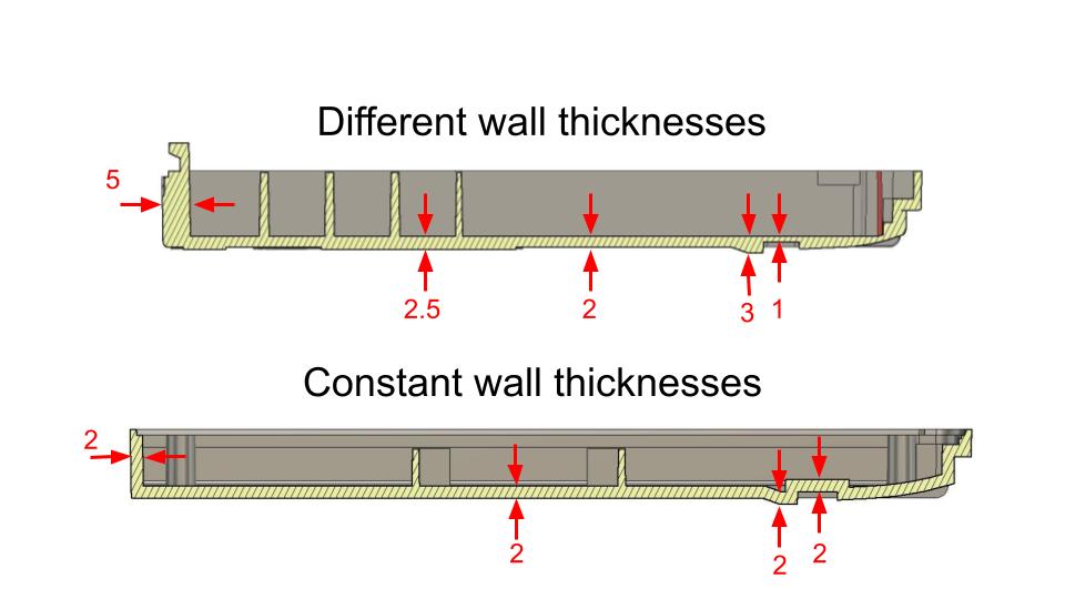 Wall thickness guidelines for injection molded plastic parts
Draft Angle Design
Draft angles allow parts to be ejected from the mold without damage. Insufficient draft leads to sticking, surface damage, and increased tooling wear.
Proper draft angles are critical for part release and tooling life. If you’re preparing for tooling, our Draft Angle Calculator can help validate your design before manufacturing OR Get a Fixed-Fee Injection Molding DFM Review
→ Read the full guide: Draft Angle in Injection Molding
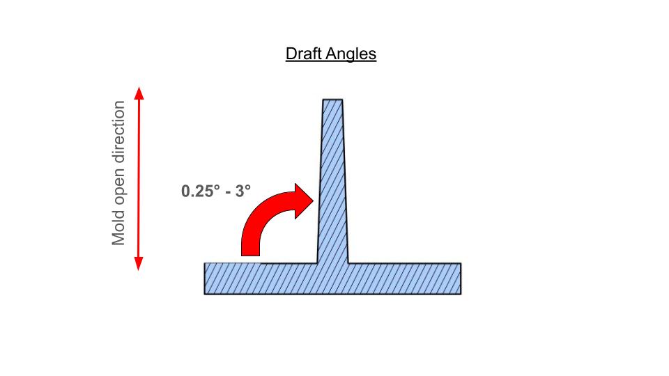 Draft Angle Design guidelines for Injection Molding
Rib Design
Ribs are used to increase stiffness without adding excessive material. Incorrect rib design can cause sink marks and poor material flow.
Get a Fixed-Fee Injection Molding DFM Review
→ Read the full guide: Rib Design for Injection Molded Parts
 Reinforcement Ribs guidelines for injection molded plastic parts
Boss Design
Bosses are used for mounting and fastening. Poorly designed bosses often lead to sink marks, cracking, or assembly issues.
These features must be carefully designed to avoid sink marks and molding defects. Our Injection Molding Design Service supports detailed feature optimization for production.
Get a Fixed-Fee Injection Molding DFM Review
→ Read the full guide: Injection Molding Boss Design
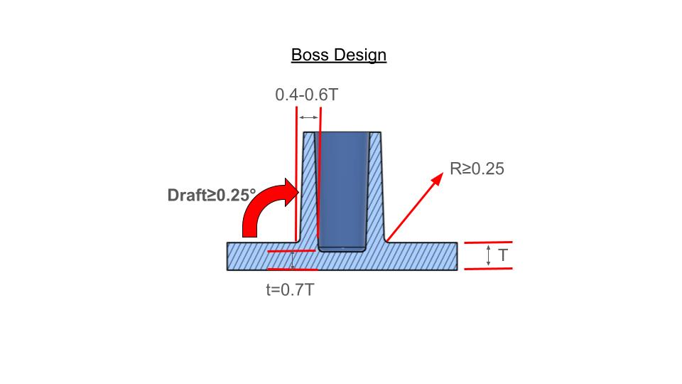 Boss Design Guidelines for Injection Molding
Snap-Fit Design
Snap-fits enable assembly without fasteners. Proper design ensures durability, flexibility, and ease of assembly.
If you are preparing for tooling, our Snap Fit Calculator can assist to validate your design OR you can also Get a Fixed-Fee Injection Molding DFM Review
→ Read the full guide: Snap-Fit Design for Plastic Parts
 Snap Fit Design Injection Molding
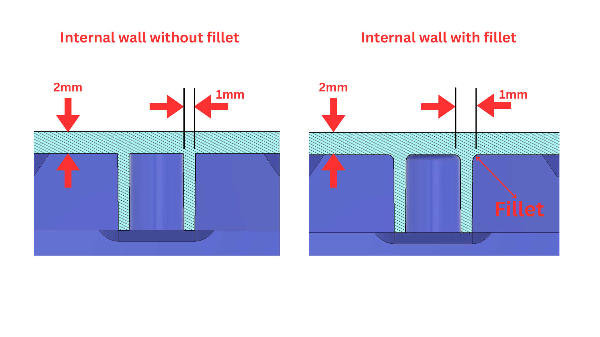
Radii and Corner Design
Sharp corners create stress concentrations and restrict material flow. Proper radii improve strength and manufacturability.
→ Read the full guide: Radii Design in Injection Molding
Parting Line Design
The parting line defines how the mold opens. Poor placement can lead to visible defects and increased tooling complexity.
→ Read the full guide: Parting Line Design for Injection Molded Parts
Gate Location and Flow
Gate placement affects material flow, weld lines, and cosmetic quality. Proper gate design is critical for part performance.
→ Read the full guide: Gate Location in Injection Molding
Material Selection
Choosing the correct plastic material affects strength, flexibility, cost, and manufacturability.
→ Read the full guide: Plastic Material Selection for Injection Molding
Common Design Mistakes
Some of the most common issues seen in production include:
large thick sections behind cosmetic surfaces
missing or insufficient draft angles
abrupt thickness transitions
poorly reinforced bosses
incorrect material selection
These issues often result in costly redesigns and delays during tooling and production.
Avoiding these issues early can save significant tooling cost and delays. Our Design for Manufacturing Consulting service helps identify these risks before production.
Real Manufacturing Example
A consumer electronics housing was designed with thick internal bosses connected directly to an external cosmetic surface.
During production, the part developed visible sink marks on the outer surface due to uneven cooling.
The issue was resolved by reducing boss thickness and adding reinforcing ribs, resulting in improved part quality and reduced cycle time.
This type of problem is common and highlights the importance of proper wall thickness control and feature design.
Design Checklist
Use this checklist when designing injection molded parts:
Include draft angles on all vertical faces
Use ribs instead of thick walls
Avoid sharp corners and include radii
Design bosses with controlled thickness
Consider cooling and material flow
Learn Injection Molding Design
Understanding these principles in theory is important, but applying them correctly in real designs requires practical experience.
Injection Molding Design Masterclass
This training covers:
complete injection molding design rules
real manufacturing case studies
practical DFM workflows
common failure scenarios
Includes 18+ design modules
View the full course →
Related Design Guides
Injection Molding Wall Thickness Design
Draft Angle in Injection Molding
Rib Design Guidelines
Boss Design for Plastic Parts
Snap-Fit Design Guide
FAQ
What are the most important injection molding design rules?
The most important rules include maintaining uniform wall thickness, adding draft angles, and designing features such as ribs and bosses correctly.
Why do injection molded parts fail in production?
Most failures are caused by poor design decisions such as uneven wall thickness, incorrect draft angles, and poor material flow.
How can I reduce injection molding costs?
Costs can be reduced by optimizing wall thickness, simplifying geometry, reducing cycle time, and designing parts for efficient manufacturing.
Conclusion
Injection molding design requires a combination of engineering knowledge and practical manufacturing experience.
By following the design guidelines outlined in this guide and exploring each topic in detail, designers can significantly improve part quality, reduce production costs, and avoid common manufacturing problems.
Start Your Injection Molding Design Review
If you are developing a plastic part, enclosure, or product for production, applying proper injection molding design principles early can reduce tooling risk, improve manufacturability, and prevent costly production issues.
Our Injection Molding Design Service helps engineering teams optimize plastic parts for tooling, assembly, and cost-effective manufacturing.
 Start your project today or contact us to discuss your design.