Sheet Metal Design Guidelines
Sheet metal is one of the most widely used manufacturing methods for enclosures, brackets, chassis systems, industrial equipment, and structural components. It is versatile, cost-effective, and well suited to both prototypes and production, but successful fabrication depends on designing parts correctly from the start.
Poor sheet metal designs often create problems during bending, welding, assembly, or fabrication. Common issues include bend cracking, distorted holes, poor alignment, excessive part count, and designs that are difficult or expensive to manufacture.
These sheet metal design guidelines explain the practical engineering rules used to develop fabrication-ready parts and assemblies. Topics include bend radius, flange design, hole placement, tolerances, structural reinforcement, and common fabrication mistakes.
Understanding these design rules helps engineering teams reduce manufacturing risk, improve assembly quality, and prepare products for efficient fabrication.
Sheet Metal Design Fundamentals
Sheet metal parts are typically manufactured from flat metal sheets using processes such as cutting, punching, bending, stamping, and welding.
A sheet metal part must be designed not only for its final shape, but also for the sequence of fabrication operations required to produce it.
Important design factors include:
• material thickness
• bend radius
• flange size
• hole location
• flat pattern development
• assembly structure
• fabrication sequence
If these constraints are ignored, the result is often higher fabrication cost, dimensional inaccuracy, or parts that cannot be produced reliably.
Companies preparing products for fabrication often benefit from early Sheet Metal Design engineering to ensure parts are practical to manufacture and ready for supplier review.
Material Thickness Guidelines
Material thickness has a major effect on part stiffness, weight, manufacturability, and cost.
Common sheet metal thicknesses include:
| Thickness | Typical Use |
|---|---|
| 1.0 mm | Light covers and small enclosures |
| 1.5 mm | Electronic housings and brackets |
| 2.0 mm | Industrial enclosures and chassis |
| 3.0 mm | Structural components and support parts |
The correct thickness depends on:
• structural requirements
• expected loads
• span lengths
• material type
• fabrication method
Using thicker material than necessary increases weight and cost, while using material that is too thin can lead to deflection or instability.
Diagram — Material Thickness Concept
Increasing thickness improves stiffness but adds weight and cost.
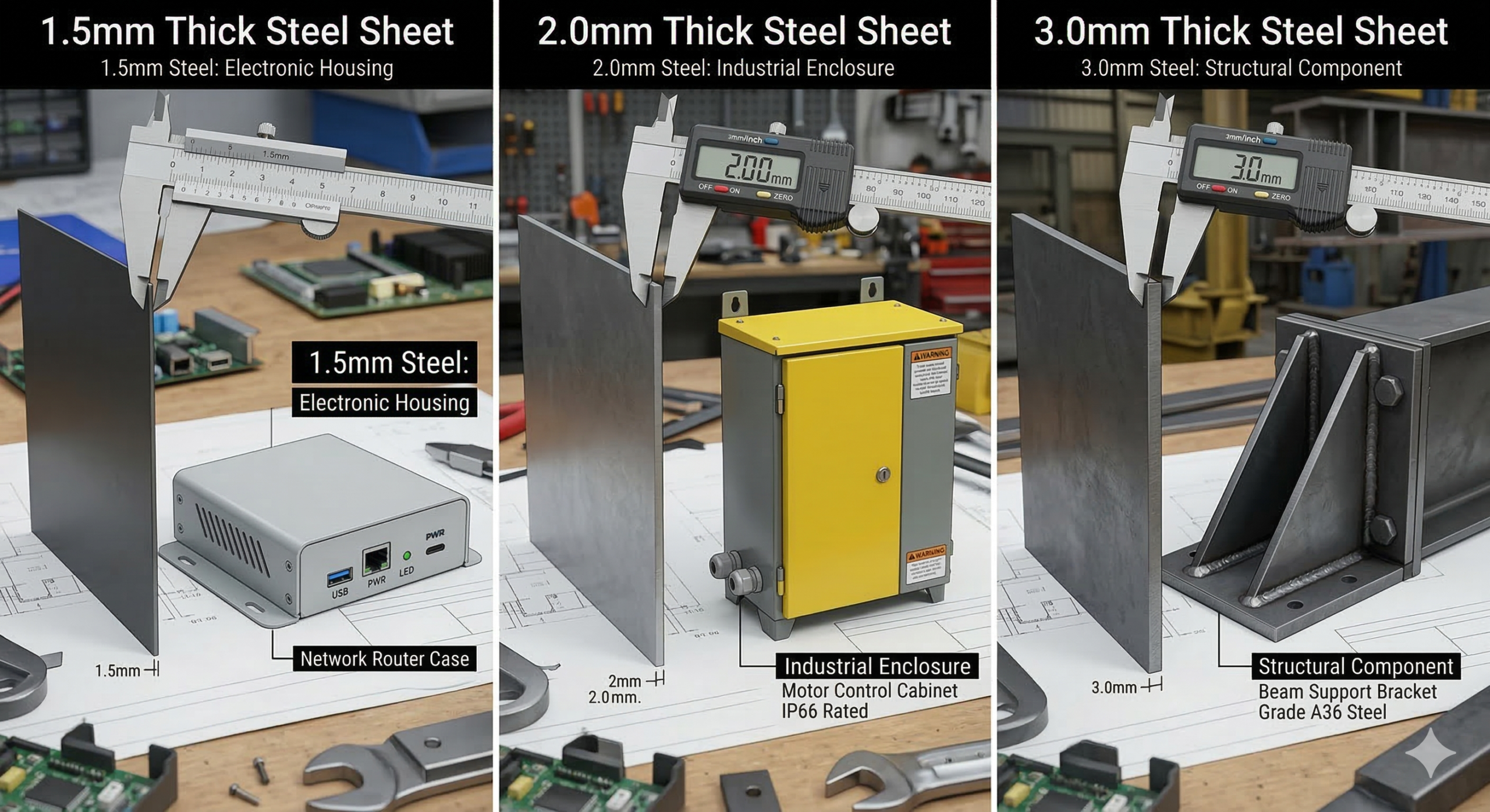
Sheet metal thickness guidelines showing typical thickness selection for enclosures, brackets, and structural components.
Bend Radius Guidelines
Bending is one of the most important sheet metal fabrication operations.
Every material and thickness combination has a practical minimum bend radius. If the bend radius is too small, the material may crack or deform during forming.
A common engineering rule is:
However, the actual requirement depends on:
• material type
• material temper
• grain direction
• fabrication method
Bend Radius Best Practices
• avoid overly sharp bends
• use consistent bend radii where possible
• confirm material-specific limitations with the fabricator
• consider bend sequence in complex parts
Correct bend radius selection helps improve part quality and reduce forming problems.
Diagram — Bend Radius
Inside Bend Radius
Typical starting rule:
Radius ≈ material thickness
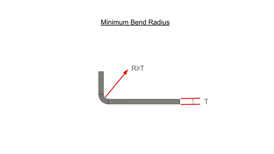 Sheet metal bend radius diagram showing inside bend radius rule relative to material thickness.
Flange Design Guidelines
Flanges are used to increase stiffness, create assembly interfaces, support fastening, and form enclosure walls.
A flange must be long enough to be bent properly. Flanges that are too short can create tooling problems or unreliable bend geometry.
Flange Design Best Practices
• provide enough flange length for bending
• avoid extremely short return flanges
• maintain consistent flange dimensions where possible
• consider tool access for brake operations
In enclosures and chassis systems, flange design has a major influence on both structural stiffness and assembly practicality.
Diagram — Flange Length
Flange must be long enough for bending
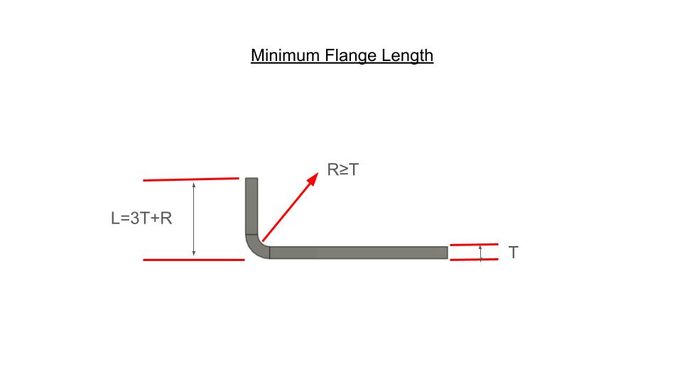 Sheet metal flange design diagram showing minimum flange length required for manufacturable bends.
Hole Placement Near Bends
Holes, slots, and cut-outs placed too close to bends may distort during forming.
This is one of the most common fabrication mistakes in sheet metal design.
Best Practices for Hole Placement
• keep holes away from bend lines
• consider bend deformation zones
• maintain sufficient clearance between holes and flange edges
• check slot orientation relative to the bend direction
A general engineering rule is to keep hole edges at least:
More clearance may be needed depending on material and fabrication method.
Diagram — Hole Distance from Bend
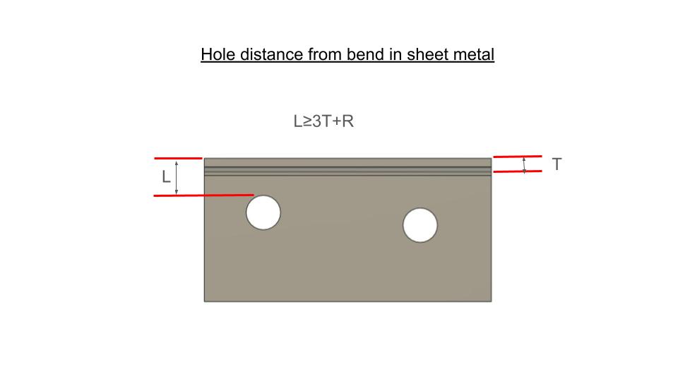 Hole distance from bend in sheet metal showing clearance needed to prevent distortion during forming.
Bend Relief Guidelines
Bend relief prevents material tearing and distortion where bends terminate near edges or cut features.
Without proper relief, stresses can build up in the corner of the bend and produce cracks or dimensional problems.
Bend Relief Best Practices
• add relief where bends terminate near edges
• use simple rectangular or obround relief shapes
• size relief according to material thickness and bend geometry
• keep relief shapes easy to fabricate
Relief features are especially important in tight packaging situations where multiple bends interact.
Sheet Metal Tolerances
Sheet metal tolerances depend on:
• material thickness
• part size
• fabrication method
• tooling accuracy
• number of bends
Typical tolerances vary between laser cutting, punching, brake forming, and welded fabrication.
Example guideline ranges:
| Feature | Typical Tolerance |
|---|---|
| Laser cut profile | ±0.1 mm to ±0.2 mm |
| Hole location | ±0.1 mm to ±0.25 mm |
| Bent flange position | ±0.2 mm to ±0.5 mm |
| Welded assembly dimensions | depends heavily on process and fixturing |
Designs that require precision assemblies should allow for realistic fabrication tolerances and not assume machined-part accuracy.
Structural Reinforcement in Sheet Metal Parts
Sheet metal parts often require reinforcement to improve stiffness without increasing material thickness excessively.
Common reinforcement strategies include:
• flanges
• return edges
• beads
• hems
• folds
• brackets
• welded support features
Well-designed reinforcement increases rigidity while maintaining fabrication efficiency.
For products combining metal structures with electronics packaging, this often works together with Electronic Enclosure Design and Design for Manufacturing Consulting.
Common Sheet Metal Design Mistakes
Many sheet metal fabrication issues are caused by a few repeated design errors.
Common mistakes include:
• bend radii that are too small
• flanges that are too short
• holes placed too close to bends
• ignoring bend relief requirements
• excessive welded part count
• unrealistic tolerances
• designs that do not consider fabrication sequence
These problems often lead to increased cost, rework, or parts that require redesign before production.
Sheet Metal Design Checklist
Before releasing a part or assembly for fabrication review, check the following:
✓ material thickness selected appropriately
✓ bend radius is realistic
✓ flange lengths are manufacturable
✓ holes are clear of bend distortion zones
✓ bend relief has been added where required
✓ tolerances are realistic for fabrication
✓ assembly structure is practical
✓ fabrication sequence has been considered
This checklist helps reduce production risk before the design is released to suppliers.
Sheet Metal Design for Enclosures and Chassis
Many sheet metal products are used as:
• electronic enclosures
• industrial control housings
• equipment chassis systems
• structural mounting frames
These applications require more than simple flat-part design. They must also consider:
• internal component clearances
• PCB mounting locations
• access panels
• cable routing
• airflow and ventilation
• fastening strategy
• serviceability
Products in this category often overlap with Electronic Enclosure Design and benefit from early Design for Manufacturing Consulting.
Learn Sheet Metal Design
We are developing practical short courses for engineers and hardware teams preparing products for manufacturing.
Upcoming topics will include:
• sheet metal design fundamentals
• bend radius and flange rules
• enclosure and chassis design
• fabrication-ready assemblies
• design for manufacturing review principles
These courses will provide deeper step-by-step examples of how sheet metal products are designed for real-world fabrication.
Related Engineering Services
If you are developing a product for fabrication or production, you may also find these services relevant:
• Sheet Metal Design Service
• Electronic Enclosure Design Service
• Injection Molding Design Service
• Design for Manufacturing Consulting
Frequently Asked Questions
What is the minimum bend radius for sheet metal?
A common starting rule is that the inside bend radius should be approximately equal to the material thickness, although this depends on the material and forming process.
How far should a hole be from a bend in sheet metal?
A common guideline is to keep the hole edge at least the bend radius plus the material thickness away from the bend, though more clearance may be needed.
Why is bend relief needed in sheet metal parts?
Bend relief helps prevent tearing and distortion where bends terminate near edges or cut-outs.
What are common sheet metal design mistakes?
Common issues include bend radii that are too small, flanges that are too short, holes placed too close to bends, and unrealistic tolerances.
What materials are commonly used in sheet metal fabrication?
Common materials include mild steel, stainless steel, and aluminum, selected according to strength, corrosion resistance, weight, and fabrication needs.
Can sheet metal be used for electronics enclosures?
Yes. Sheet metal is widely used for electronic housings, control cabinets, chassis systems, and industrial enclosures because it provides strength and good manufacturability.