Injection Molding Design Guidelines
These injection molding design guidelines explain the engineering rules used to develop plastic parts ready for production.
Injection molding is one of the most widely used manufacturing processes for plastic products. It enables the production of complex, high-precision parts at scale, but only when the product has been engineered correctly for the manufacturing process.
Designing plastic parts without considering tooling constraints, cooling behavior, and material flow can result in expensive redesigns, tooling modifications, and production delays.
These injection molding design guidelines cover the key engineering principles used to develop plastic components that are ready for manufacturing. Topics include wall thickness control, draft angles, rib structures, boss design, snap fits, tolerances, and common manufacturability issues.
Understanding these rules helps product teams reduce tooling risk, improve part performance, and move from prototype to production more efficiently.
Injection Molding Design Fundamentals
Injection molding works by injecting molten plastic into a precision-machined mold cavity where the material cools and solidifies into the final part geometry.
While the process allows for extremely complex shapes, successful production depends heavily on designing the part correctly from the beginning.
Key manufacturing considerations include:
• consistent wall thickness
• proper draft angles for mold release
• structural reinforcement using ribs
• correct boss and fastening geometry
• controlled tolerances
• minimized undercuts
Ignoring these constraints during product development often leads to costly tooling revisions once molds have already been manufactured.
Companies preparing products for manufacturing often benefit from early Injection Molding Design engineering to ensure that parts are ready for tooling discussions and supplier engagement.
Wall Thickness Guidelines
Wall thickness is one of the most important factors in injection molding design.
Thick sections cool slower than thin sections, which can lead to warping, internal stress, and cosmetic defects such as sink marks.
The goal is to maintain consistent wall thickness throughout the part whenever possible.
Typical Wall Thickness Ranges
| Material | Typical Wall Thickness |
|---|---|
| ABS | 1.2 – 3.5 mm |
| Polycarbonate | 1.0 – 3.0 mm |
| Polypropylene | 0.8 – 3.8 mm |
| Nylon | 1.0 – 3.0 mm |
Wall Thickness Best Practices
• keep walls consistent
• avoid sudden transitions
• use ribs for reinforcement instead of thicker walls
• design gradual thickness transitions when required
Consistent wall thickness helps ensure uniform cooling and reduces internal stresses within the molded component.
Diagram — Wall Thickness Strategy
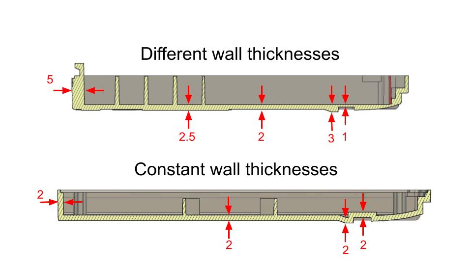 Wall thickness guidelines for injection molded plastic parts
Use Consistent Wall thickness
Thick section may cause sink & warping
Draft Angle Guidelines
Draft angles are required so molded parts can be removed from the mold without damaging the part or the tool.
Without draft, the plastic surface drags along the mold wall during ejection, creating scratches or part deformation.
Typical Draft Angle Values
Minimum recommended draft:
2° preferred
3°+ for textured surfaces
Draft requirements depend on material type, part depth, and surface finish.
Adding draft early in the design stage prevents tooling modifications later.
Draft Angle Diagram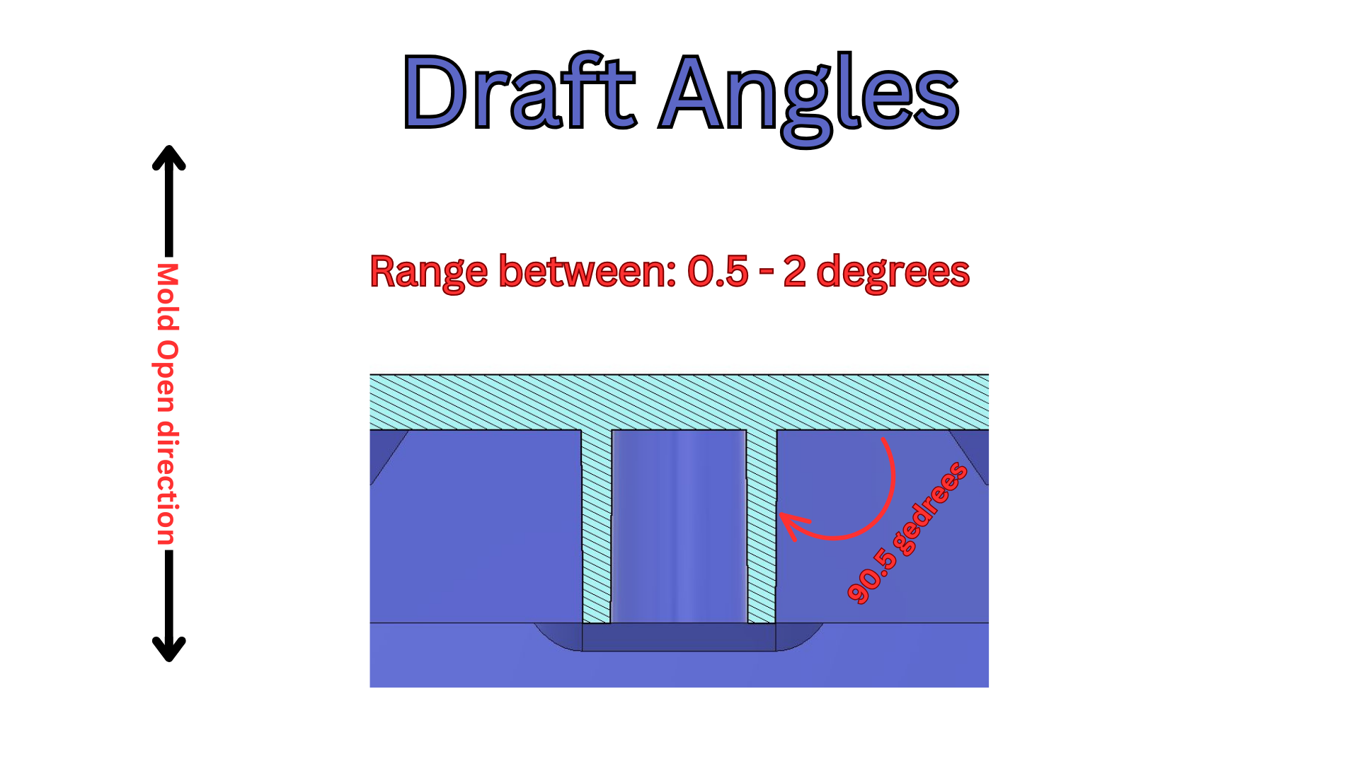 Draft Angle guidelines for injection molded plastic parts
Rib Design Guidelines
Ribs are used to strengthen plastic parts without increasing overall wall thickness.
Instead of thickening walls, ribs add structural reinforcement while maintaining proper cooling behavior.
Rib Design Rule
If ribs are too thick, they can cause visible sink marks on the opposite surface of the part.
Rib Design Best Practices
• maintain correct rib thickness
• limit rib height
• include draft on rib walls
• avoid rib intersections that trap material
Ribs are commonly used in electronic enclosures and structural plastic components.
Rib Design Diagram
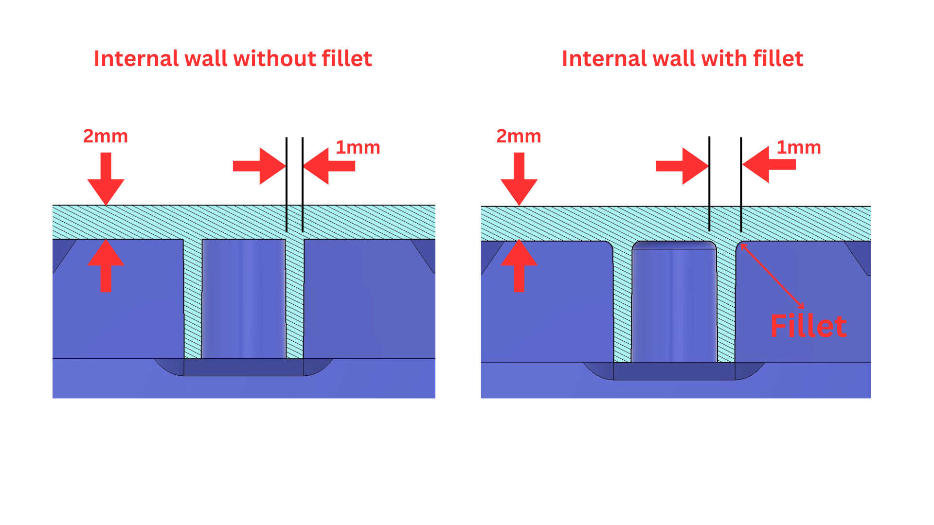 Reinforcement Ribs guidelines for injection molded plastic parts
Boss Design Guidelines
Bosses are cylindrical features used for fasteners, inserts, and assembly alignment.
They are commonly used to mount PCBs, secure enclosures, or provide attachment points for screws.
Boss Design Considerations
• reinforce bosses with ribs
• maintain proper spacing between bosses
• avoid thick boss bases
• support bosses with surrounding structure
Unsupported bosses can lead to cracking or deformation during assembly.
Boss Design Diagram
Screw Boss
Snap Fit Design Guidelines
Snap fits allow plastic parts to assemble without screws or adhesives.
They are commonly used in consumer products, enclosures, and small devices.
The most common snap fit type is the cantilever snap fit.
Snap Fit Design Factors
• material flexibility
• engagement depth
• release direction
• repeated assembly cycles
Designing snap fits requires balancing retention strength with material fatigue limits.
Snap Fit Diagram
Undercuts in Injection Molding
Undercuts occur when a feature prevents the part from being ejected from the mold in a straight direction.
Examples include:
• side holes
• locking features
• reverse angles
Undercuts require additional mold mechanisms such as slides or lifters, which increase tooling cost and complexity.
Whenever possible, designs should minimize or eliminate unnecessary undercuts.
Injection Molding Tolerances
Plastic parts cannot achieve the same precision as machined metal components.
Typical tolerances depend on:
• material type
• part size
• mold quality
• cooling conditions
Typical injection molding tolerances:
| Dimension | Typical Tolerance |
|---|---|
| Small features | ±0.05 mm |
| General dimensions | ±0.1 mm |
| Large components | ±0.2 mm |
Understanding realistic tolerances is important when designing mating components or assemblies.
Common Injection Molding Design Mistakes
Many plastic parts fail during manufacturing because fundamental design rules were not considered early.
Common mistakes include:
• inconsistent wall thickness
• missing draft angles
• overly thick ribs or bosses
• excessive undercuts
• poorly planned assembly features
These issues often become visible only after molds are produced, when design changes become expensive.
Injection Molding Design Checklist
Before sending a part for tooling review, check the following:
✓ consistent wall thickness
✓ draft angles applied
✓ ribs correctly proportioned
✓ bosses reinforced
✓ undercuts minimized
✓ assembly strategy defined
This checklist helps ensure the design is ready for manufacturing discussions with suppliers.
Injection Molding Design for Electronic Enclosures
Many injection molded components are developed as part of electronic product enclosures.
These designs must account for additional considerations including:
• PCB mounting structures
• screw bosses and internal ribs
• connector openings
• ventilation or sealing features
Products combining plastic housings with internal electronics benefit from careful electronic enclosure architecture before tooling begins.
Learn Injection Molding Design
We are developing practical short courses for engineers and hardware teams preparing products for manufacturing.
Upcoming topics include:
• wall thickness engineering
• rib and boss design strategies
• snap fit development
• enclosure architecture
• manufacturing design reviews
These courses will provide deeper, step-by-step examples of designing injection molded products for production.
Related Engineering Services
Injection Molding Design
Electronic Enclosure Design
Sheet Metal Design
Design for Manufacturing Consulting
Frequently Asked Questions
What is the best wall thickness for injection molding?
Most plastic parts fall within the range of 1–3 mm wall thickness, depending on the material and structural requirements.
How much draft angle is required?
Most injection molded parts require at least 1° draft, with 2° or more preferred for reliable mold release.
How thick should ribs be in plastic parts?
Rib thickness should typically be 50–70% of the main wall thickness to prevent sink marks and maintain structural strength.
What are the most common injection molding design mistakes?
The most common issues include inconsistent wall thickness, missing draft angles, poorly designed ribs or bosses, and unnecessary undercuts.