How to Design for Injection Molding: 7 Rules to Slash Production Costs
Published: September 17, 2025
Introduction
Are you an engineer, product designer, or startup founder looking to bring a plastic part to market efficiently and cost-effectively? Mastering the principles of Design for Injection Molding (DFIM) is crucial for reducing production costs and avoiding common manufacturing pitfalls. Design for Injection Molding (DFIM) refers to the process of designing plastic parts specifically for the injection molding process, ensuring that the parts can be manufactured efficiently, with high quality, and at a lower cost. Closely related is Design for Manufacturability (DFM), a broader concept that encompasses all aspects of designing products for ease of manufacturing, not just injection molding.
This article covers the essential rules and best practices for design for injection molding, helping engineers and product designers reduce costs and improve manufacturability. We’ll clarify the relationship between mold design, part design, and DFM, and provide actionable guidance through 7 essential rules for design for injection molding. By mastering these rules, you’ll be able to streamline your product development, minimize waste, and avoid costly manufacturing errors.
A solid understanding of design considerations—such as wall thickness, draft angles, surface textures, and material choices—forms the foundation for the rules and tips discussed in this article.
Moreover, our animated exploded views showcase manufacturable designs—contact us!
Understanding Design for Injection Molding
Design for Injection Molding (DFIM) is the practice of designing plastic parts specifically to be manufactured using the injection molding process. It involves optimizing part geometry, material selection, and features to ensure manufacturability, cost-effectiveness, and high quality. Design for Manufacturability (DFM), on the other hand, is a broader engineering approach that focuses on designing products for ease of manufacturing across various processes, including but not limited to injection molding.
How do mold design, part design, and DFM relate?
Part design refers to the geometry, features, and specifications of the plastic component itself.
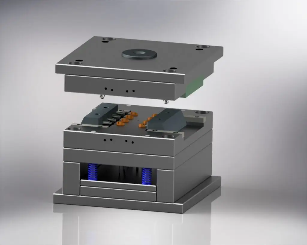
Mold design involves creating the tooling (the mold) that shapes the molten plastic into the final part.
DFM bridges these two by ensuring that the part design is compatible with efficient mold design and manufacturing processes, reducing costs and defects.
Effective injection mold design is crucial for achieving efficient, high-quality production, as it directly impacts part quality, ejection, and overall manufacturing performance. Poor choices lead to defects, as noted in Industry Insights. For instance, uniform features minimize issues.
With these foundational concepts in mind, let’s establish some basic knowledge about the injection molding process before diving into the key rules for effective injection molding design.
Injection Molding Machine and Production
The injection molding machine is the heart of the injection molding process, responsible for transforming raw plastic material into finished plastic parts. Understanding its components and operation is essential for aligning your part and mold design with manufacturing capabilities.
Main Components of Injection Molding Machine
Injection Unit: Melts and injects the plastic material.
Mold Cavity: The hollow space where the molten plastic takes shape.
Clamping/Ejector Unit: Holds the mold closed during the molding cycle and ejects the completed part.
Optimizing the Molding Cycle
To produce plastic parts efficiently:
Match the injection molding machine’s capacity to your part and mold design.
Choose a molding machine with the right clamping force and injection capacity to ensure the mold cavity is filled properly, preventing defects and reducing production costs.
Optimize the injection molding cycle by fine-tuning parameters like injection speed, pressure, and temperature to improve productivity and part quality.
Matching Machine to Mold Design
A well-chosen injection molding machine, paired with a robust mold design and the right plastic material, allows manufacturers to repeat the molding process thousands of times with consistent results. By focusing on these factors, you can streamline your manufacturing process, minimize waste, and keep production costs in check.
Now that you understand the basics of the injection molding process and equipment, let’s explore the 7 essential rules for designing parts for injection molding.
Rule 1: Uniform Wall Thickness
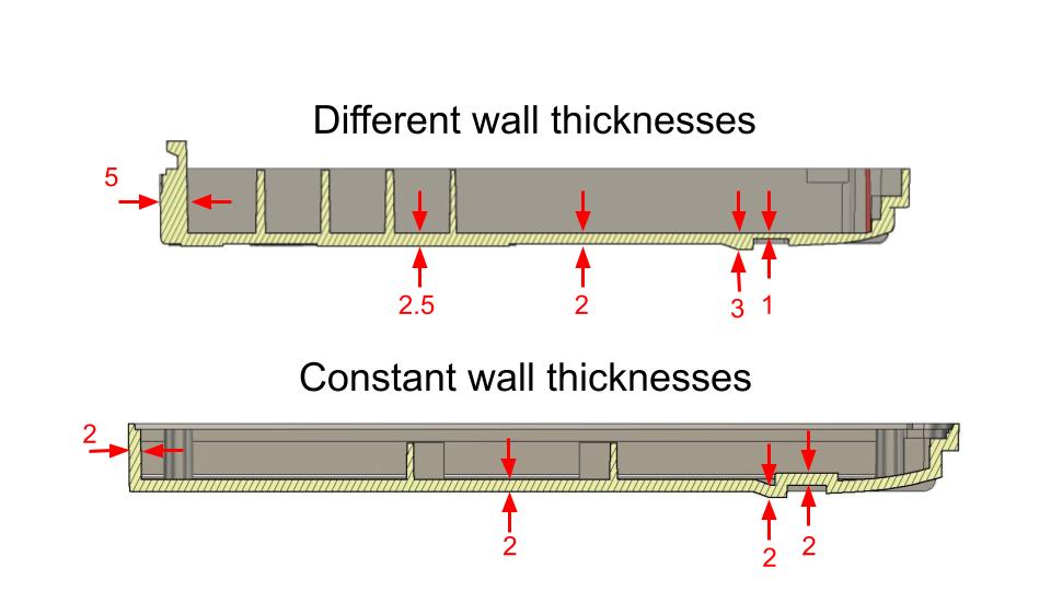
Wall Thickness Guidelines
Consistent wall thickness is key to molding design. Maintaining a constant wall thickness and a uniform nominal wall helps prevent defects such as warping, sink marks, and uneven cooling. Variations cause warping. For example, thick sections cool slower, creating shrinkage. Selecting the proper wall thickness, including maintaining a minimum wall thickness, is essential for manufacturability, structural integrity, and part quality. Material thickness also influences stress concentration around sharp corners and fillet radii, so choose radii proportional to the material thickness to improve flow and reduce internal stresses. When dealing with thick wall sections or thick walls, be aware of challenges like sink marks and longer cooling times; strategies such as coring or adding ribbing can help mitigate these issues. For thin wall and thin wall injection molding, benefits include reduced material use and faster cycle times, but careful design is needed to manage flow, cooling, and structural integrity. Therefore, use 1.5-3 mm thickness and gradual transitions. This reduces cycle times and boosts efficiency.
Pro Tip: Use simulation software to analyze distribution.
Rule 2: Draft Angles for Ejection
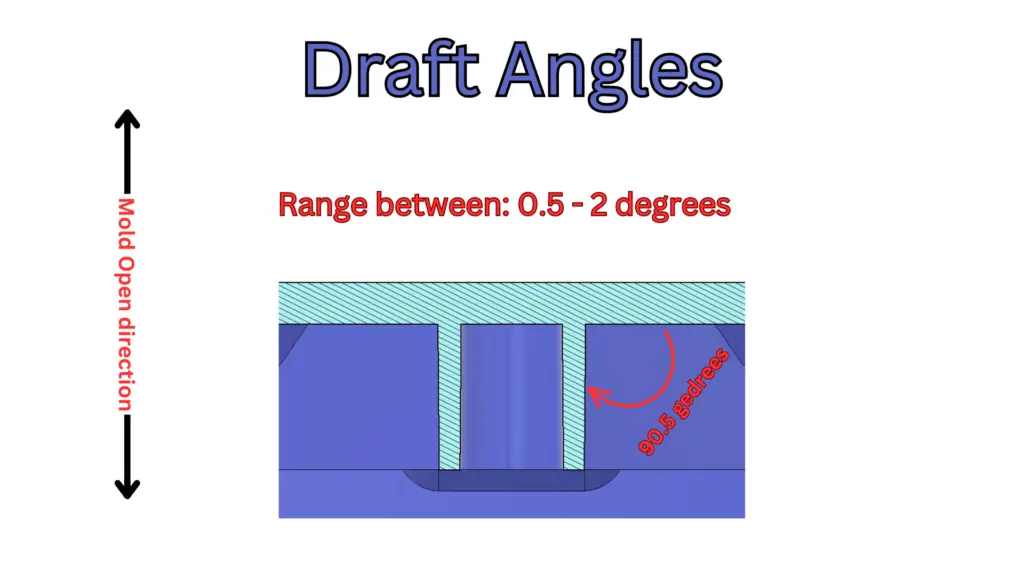
Draft Angle Recommendations
Draft angles are critical for Design for Injection Molding. Without them, friction damages parts. For instance, aim for 0.5–2 degrees. Textured surfaces need up to 5 degrees. Insufficient draft angles can cause drag marks during ejection, as the part scrapes against the mold surface; increasing draft helps prevent this defect. Consequently, this extends mold life and cuts costs.
Real-World Example: A client reduced failures by 70% with 1.5-degree drafts.
Rule 3: Optimize Ribs and Gussets
Rib and Gusset Design Tips
Ribs strengthen parts in molding design. However, improper design causes sink marks. For example, keep rib thickness below 60% of wall. Maintain 3:1 height-to-thickness ratio. Align with flow direction. Well-designed ribs help avoid stress concentrations that can weaken the part by minimizing sharp transitions and ensuring uniform support. Thus, a company eliminated defects by adjusting rib thickness.
Rule 4: Radii for Injection Molding DFM
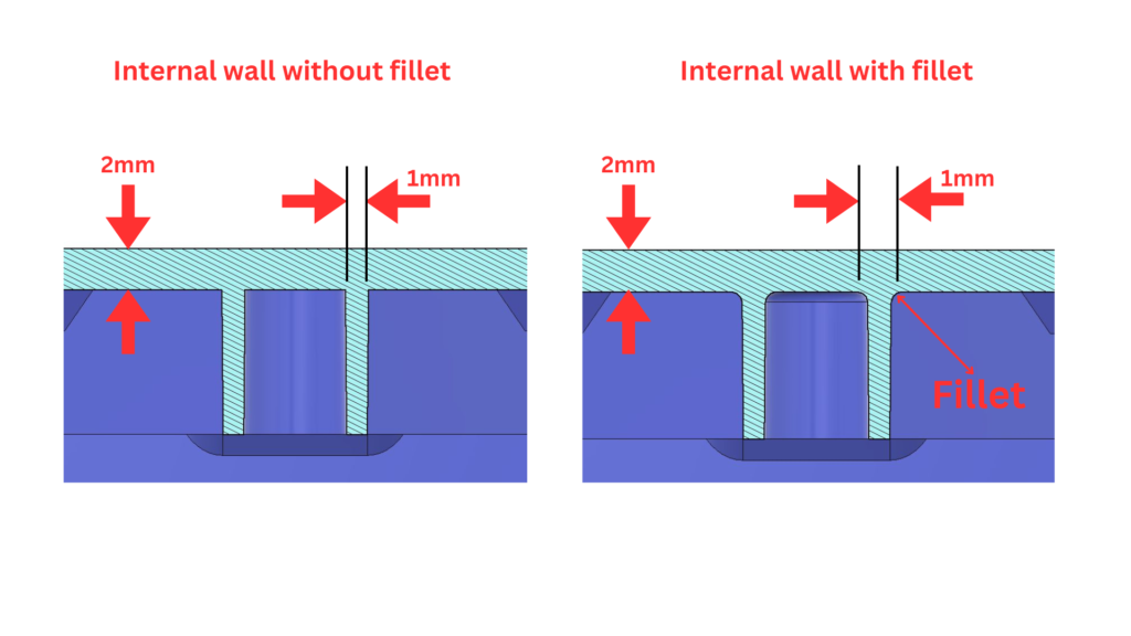
Radii and Corner Transition Guidelines
Sharp corners create stress in DFM. Incorporating smooth transitions between different wall thicknesses or features, such as using chamfers or fillets, further reduces stress and improves part durability. Incorporate radii (0.5x wall thickness) to improve flow. For instance, a 1 mm radius reduces turbulence. Consequently, this cuts scrap rates.
Rule 5: Strategize Gate Placement
Gate Placement Best Practices
Gate placement affects filling in molding design. Poor placement causes defects. For example, position gates on non-visible surfaces. Use simulations to predict patterns. Thus, relocating a gate eliminated weld lines.
There are several types of gates used in design for injection molding, each with specific advantages:
Sub gates (e.g., banana gates, tunnel gates, smiley gates): Allow for automatic trimming and can be positioned away from the parting line for greater flexibility.
Hot tip gates: Commonly used in hot runner systems for high-volume production, providing precise and uniform flow, especially for complex or rounded parts.
The gate and runner system (the network of channels that directs molten plastic into the mold cavity) is critical for ensuring proper filling, flow control, and pressure distribution throughout the injection molding process.
Rule 6: Minimize Undercuts
Undercut Reduction Strategies
Undercuts complicate tooling in DFM. Redesign with snap-fits or living hinges—a living hinge is a thin, flexible section of plastic that connects two rigid sections, allowing them to bend without breaking. A well-designed living hinge, with optimized geometry, thickness, and material selection, is crucial for durability and function when replacing undercuts. For low-volume, use aluminum molds. However, weigh against efficiency goals.
Rule 7: Select Materials Wisely
Material Selection Tips
Material choice impacts molding design. For example:
Injection molding materials include a wide range of thermoplastic materials, each offering unique properties for different applications.
Polypropylene (PP): Excellent flow.
ABS: Balances strength.
PEEK: High-performance, costly.
Polystyrene and polypropylene: Valued for cost-effectiveness and chemical resistance, but may have limitations for mechanical use.
Plastic resin selection is critical, as the molecular structure and bonds of the resin influence stress development during cooling, affecting part quality and defect rates.
Granular plastic is the raw material fed into the injection molding machine, where it is melted and injected into molds to form finished parts.
For living hinges or overmolded parts (where one material is molded over another to create a composite part), choosing a flexible material ensures durability and proper function.
Thus, collaborate with suppliers for alignment.
Ejector Pins and Part Ejection
Ejector Pin Function and Placement
Ejector pins are essential for removing injection molded parts from the mold cavity once the molding cycle is complete. Located on the B-side of the mold, these pins push the cooled, solidified part out of the mold, ensuring a smooth and efficient ejection process.
Ejector Pin Design Considerations
The design and placement of ejector pins are critical to maintaining part quality and protecting both the molded parts and the mold itself. Factors such as pin diameter, length, and strategic location must be carefully considered. For example, using ejector pins with sufficient diameter and length helps prevent parts from sticking in the mold cavity, reducing the risk of part distortion or mold damage.
Strategically placing ejector pins in areas where the part is most likely to stick can further facilitate easy ejection and minimize production costs. Proper ejector pin design not only ensures the integrity of your injection molded parts but also extends the life of your mold, making your overall injection molding process more efficient and cost-effective.
With a solid understanding of ejection, let’s examine common defects and how to solve them.
Common Molding Defects and Solutions
Even with a well-designed injection molding process, defects like sink marks, warping, and uneven surface finish can occur. Addressing these issues early in the design and manufacturing process is key to producing high-quality plastic parts and keeping production costs low.
Common Defects and Solutions
Sink Marks
Description: Depressions often appear in thick sections of a part.
Solution: Maintain a consistent wall thickness and use ribs or coring to avoid overly thick areas. Optimize the injection molding cycle—such as adjusting cooling time and pressure.
Warping
Description: Warping happens when parts cool unevenly or when the plastic material shrinks inconsistently.
Solution: Ensure uniform cooling, use a mold with proper draft angles, and select a plastic material with low shrinkage.
Uneven Surface Finish
Description: A poor surface finish can result from inadequate mold surface quality or improper material flow.
Solution: Use a high-quality mold surface and optimize material flow during the molding process to improve the appearance and consistency of your molded parts.
By addressing these common defects, you can further optimize your injection molding process. Next, let’s answer some frequently asked questions about DFM.
FAQ: What is the Goal of DFM in Injection Molding?
The goal of DFM (Design for Manufacturability) in Injection Molding is to optimize designs for efficient production, reducing costs and defects. DFM also streamlines mold building by ensuring designs are optimized for manufacturability and cost, taking into account mold design considerations and material selection for mold construction. For example, it ensures uniform thickness and draft angles to minimize cycle times. Consequently, companies save 20-40% on tooling, as per our Design for Injection Molding Course. Therefore, DFM bridges design and manufacturing for success.
Case Study: Injection Molding DFM Success
A medical device startup faced high scrap rates due to uneven wall thickness in their syringe housing. By applying Injection Molding DFM, we adjusted thickness to 2 mm and addressed material shrinkage during cooling, reducing defects by 35% and saving $60,000. We also defined the a and b sides and optimized the parting line to improve mold design and surface finish. During each cycle, the mold closes, plastic is injected, and after cooling, the mold opens so the halves of the mold can separate and the part is ejected. The injection molder played a key role in implementing these DFM changes and producing consistent parts. Subsequently, production sped up by 25%.
Another case involved a toy manufacturer. Their complex mold design raised tooling costs. We simplified gates and radii, and used the same mold for multiple components, cutting costs by 30%. These cases show DFM’s impact.
Conclusion
Injection molding doesn’t have to be costly. By integrating these rules into Design for Injection Molding, you slash expenses and accelerate market entry. At 3DDFM, we transform concepts into manufacturable designs with $75/hr expertise. For learning, enroll in our online course or schedule a consultation.
Summary Checklist: 7 Rules for Design for Injection Molding
For quick reference, here are the 7 essential rules to follow:
Uniform Wall Thickness: Maintain consistent wall thickness (1.5–3 mm) and gradual transitions to prevent defects.
Draft Angles for Ejection: Apply 0.5–2 degrees of draft (up to 5 degrees for textured surfaces) to aid part removal and protect the mold.
Optimize Ribs and Gussets: Keep rib thickness below 60% of wall, use a 3:1 height-to-thickness ratio, and align ribs with flow direction.
Radii for Injection Molding DFM: Use radii (0.5x wall thickness) and smooth transitions to reduce stress and improve flow.
Strategize Gate Placement: Place gates on non-visible surfaces, use simulations, and select the appropriate gate and runner system for your part.
Minimize Undercuts: Redesign with snap-fits or living hinges to simplify tooling and reduce costs.
Select Materials Wisely: Choose materials based on flow, strength, and application needs; consult suppliers for the best fit.
By following these rules, you’ll improve manufacturability, reduce costs, and achieve higher quality in your injection molded parts.
Manufacturing Engineering Services:
Injection Molding Design
Electronic Enclosure Design
Sheet Metal Design
Design for Manufacturing Consulting