Sheet Metal Design: Optimize Your Designs for Manufacturing
Published: February 2, 2026
Table of Contents
Introduction
Sheet metal design is essential for creating cost-effective, manufacturable parts that meet both functional and aesthetic requirements. This comprehensive guide covers the fundamentals of sheet metal design, including material selection, bending and forming, flat pattern development, assembly and fastening, DFM (Design for Manufacturability) best practices, common mistakes, the role of technology, and real-world case studies.
It is intended for engineers, product designers, and startups looking to optimize their designs for manufacturing efficiency and cost savings. Whether you are new to sheet metal or seeking to refine your process, understanding these principles will help you avoid costly errors and streamline production.
What is Sheet Metal Design?
Sheet metal design involves creating parts and assemblies from thin, flat metal sheets that are cut, bent, and formed into desired shapes. This process is widely used in industries such as automotive, aerospace, electronics, and consumer products due to its versatility, strength, and cost-effectiveness. Good sheet metal design ensures parts are easy to manufacture, assemble, and scale, making it a critical skill for anyone involved in product development.
Why Sheet Metal DFM Matters
DFM (Design for Manufacturability) is the process of optimizing a design to make manufacturing easier and more cost-effective. In sheet metal fabrication, DFM minimizes waste, reduces cycle times, and enhances part quality. For example, optimizing bends and clearly defining bend lines can cut material costs by 15-25%.
Secondary processing, such as deburring or surface finishing, can further improve the quality and consistency of sheet metal parts after initial fabrication. By applying DFM principles early, engineers and startups can avoid costly redesigns and ensure high-quality, affordable products.
With the importance of DFM established, the next step is selecting the right material for your sheet metal project.
Material Selection for Sheet Metal Design
Choosing the appropriate material is foundational to successful sheet metal design. The material you select directly influences manufacturability, cost, and the performance of the final part.
Common Sheet Metal Materials
Aluminum: Lightweight, high strength-to-weight ratio, excellent corrosion resistance.
Stainless Steel: Superior durability, corrosion resistance, suitable for harsh environments.
Cold-Rolled Steel: Smooth finish, uniform wall thickness, good for precision parts.
Hot-Rolled Steel: Cost-effective, ideal for larger, less precise components.
Material Properties
Key properties to consider when selecting sheet metal materials include:
Strength: Ability to withstand loads without deforming.
Corrosion Resistance: Resistance to rust and environmental damage.
Formability: Ease of bending and shaping without cracking.
Weldability: Suitability for joining processes.
Thickness: Affects bendability and final part quality.
Material Selection Tips
Match material properties to the intended application and fabrication process.
Consider how material thickness and uniform wall thickness affect bendability and flat pattern development.
The choice of material directly influences the minimum bend radius and the required bend allowance (the extra material needed to account for stretching during bending).
With the right material chosen, the next step is understanding how to shape it effectively—covered in the following section on bending and forming.
Bending and Forming Fundamentals
Bending and forming are at the heart of sheet metal fabrication, transforming flat sheets into functional, three-dimensional components. The process involves applying force along a bend axis to achieve specific angles and shapes.
Bend Radius
The bend radius is the inside radius of the bend, typically at least equal to the material thickness. Using the correct bend radius helps prevent cracking and excessive deformation, especially in thicker materials.
K Factor and Bend Allowance
The k factor is a ratio that represents the location of the neutral axis relative to the material thickness during bending. Accurately calculating the k factor allows designers to determine the bend allowance—the length of the neutral axis between the bend lines, which is critical for ensuring the final dimensions of the bent part match the design intent.
K Factor: Ratio of the distance from the inside bend to the neutral axis, divided by the material thickness.
Bend Allowance: The arc length of the bend’s neutral axis, used to develop accurate flat patterns.
Heat Affected Zone (HAZ)
The Heat Affected Zone (HAZ) is the area of the material that has had its properties altered by the heat of processes like laser cutting. The HAZ can impact subsequent bending operations by making the material more brittle or prone to distortion.
By understanding these fundamentals and applying best practices, teams can produce high-quality sheet metal components that meet tight tolerances and functional requirements.
Once you understand bending and forming, the next step is to develop accurate flat patterns for manufacturing.
Flat Pattern Development Essentials
Flat pattern development is a vital step in the sheet metal process, serving as the blueprint for transforming a flat sheet into a finished, three-dimensional part. Accurate flat patterns ensure the final product meets dimensional accuracy standards.
Bend Relief and Feature Sizing
Bend Relief: Small cutouts at the ends of bends to prevent tearing or distortion.
Minimum Feature Sizes: Adhere to minimum hole diameter and flange length to ensure manufacturability and structural integrity.
Minimum inside diameter should typically equal the material thickness.
Tooling and Minimum Distances
Tooling Choice: The use of a punch press or press brake can influence the flat pattern, especially for unique features or tight tolerances.
Minimum Distances: Maintain proper minimum distances between holes, edges, and bends to prevent deformation and ensure smooth assembly.
Once the flat pattern is developed, attention turns to key design considerations that impact manufacturability.
Top 5 DFM Considerations
DFM (Design for Manufacturability) addresses critical design factors to ensure efficient and cost-effective sheet metal fabrication. Here are the top five considerations:
Material Selection
Choose alloys like aluminum or mild steel for strength and cost.
Material properties such as ductility, thickness, and variability require tailored forming techniques and influence laser cutting parameters.
Bend Radii
Use minimum bend radii (often 1x or more times the material thickness) to avoid cracks.
Consistent radii across all bends control springback and prevent deformation.
Tolerances
Set realistic tolerances (e.g., ±0.1mm) to reduce machining costs.
Cut-Outs
Minimize holes near bends to prevent distortion.
Maintain minimum distances between holes and edges (typically several times the material thickness).
Welding Jigs and Edge Finishing
Design jigs to reduce warping during welding.
Round or curl sharp edges for safety and manufacturability.
For example, using DFM principles ensures cost-effective, high-quality parts by addressing these considerations early in the design process.
Common Sheet Metal Design Mistakes
Avoiding common mistakes is crucial for efficient production:
Inconsistent Bend Radii: Causes cracking and higher scrap rates.
Tight Tolerances: Unnecessarily increases machining costs.
Poor Cut-Out Placement: Leads to distortion during bending, especially near bends or with features like louvers or extrusions.
Ignoring Welding Warping: Results in defective parts.
By recognizing and addressing these pitfalls, you can ensure smoother production and higher quality outcomes.
Steps to Implement Sheet Metal DFM
Implementing DFM in sheet metal design involves a structured, step-by-step approach:
Design Review
Analyze CAD models for bend radii and tolerances using tools like SolidWorks.
Check countersink features for correct major diameters and ensure fasteners can be inserted flush.
Prototype Testing
Use laser cutting to catch issues early, saving 15-20% on revisions.
Check embossed features to ensure maximum depth does not exceed recommended limits (typically ≤3x material thickness).
Material Optimization
Select cost-effective alloys with engineers to balance performance and price.
Tooling Collaboration
Work with fabricators to simplify designs, reducing costs by 20-30%.
Validation
Test with short runs to ensure scalability and quality.
Review the design for cosmetic appearance and ensure it meets aesthetic requirements.
Following these steps streamlines production and reduces the risk of costly errors.
Assembly and Fastening Techniques
Effective assembly and fastening are essential for ensuring the structural integrity and functionality of sheet metal components. The choice of fastening method should align with material properties, sheet thickness, and design intent.
Common Fastening Techniques
Fastening Method | Advantages | Considerations |
|---|---|---|
Welding | Strong, permanent joints | Can cause warping; requires jigs |
Riveting | Quick, reliable, no heat | May require access to both sides |
Screwing | Removable, easy assembly | May loosen over time |
PEM Inserts | Provide strong threads in thin sheets | Require precise hole sizing |
Fastening Method
Advantages
Considerations
Welding
Strong, permanent joints
Can cause warping; requires jigs
Riveting
Quick, reliable, no heat
May require access to both sides
Screwing
Removable, easy assembly
May loosen over time
PEM Inserts
Provide strong threads in thin sheets
Require precise hole sizing
PEM inserts are specialized fasteners pressed into sheet metal to provide strong, reusable threads in thin materials.
To avoid material distortion, maintain minimum distances between holes, slots, and edges. Surface treatments like powder coating can add thickness, so account for these during design to ensure proper fit.
By considering these practical aspects, you can achieve reliable, high-quality assemblies that meet both functional and aesthetic requirements.
Role of Technology in Sheet Metal DFM
Modern technology enhances every stage of sheet metal DFM:
Laser Cutting Software: Optimizes nesting to minimize waste; material type selection is crucial for optimal results.
Bend Simulation: Predicts distortion and catches issues early.
3D Printing: Enables rapid prototyping for fit and function testing.
AI Tools: Suggest material swaps and design changes for cost savings.
Secondary processing, such as deburring or surface finishing, can further improve part quality and consistency.
By leveraging these technologies, teams can streamline production and reduce errors.
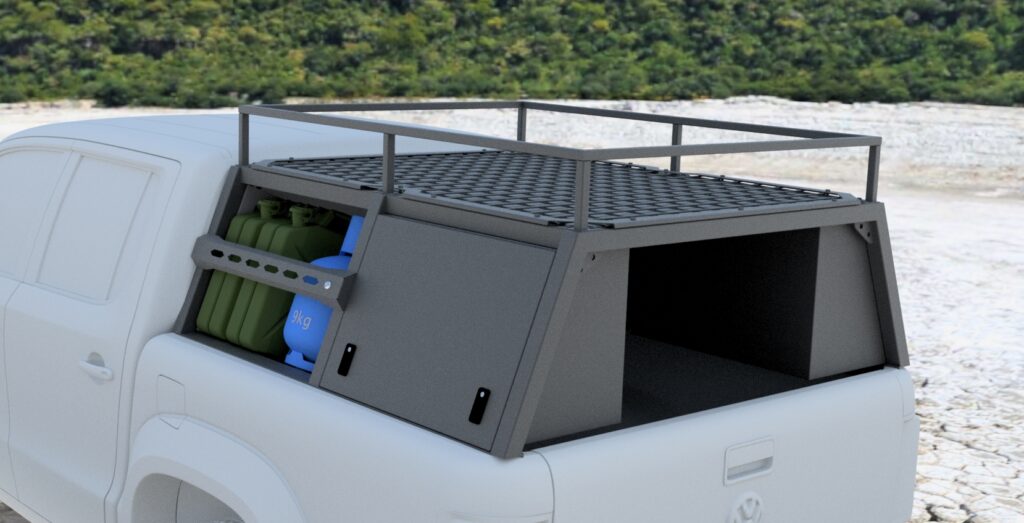
Case Study: Optimizing a Load Bin Organizer
Our Load Bin Organizer project demonstrates the power of DFM in real-world applications. Initially, the design featured complex bends and cut-outs, risking $5,000 in extra tooling costs. By applying DFM principles, we achieved the following:
Added optimal bend radii to prevent cracking.
Clearly defined bend lines for accurate, consistent bends.
Standardized tolerances for laser cutting and bending, saving 25% on fabrication.
Used welding jigs to minimize warping during assembly.
Applied guidelines for hem return length (6x material thickness), hem radius, and ensured the minimum inside diameter equals the material thickness for both open and closed hems.
Incorporated a circular roll on select edges to strengthen and remove sharpness, improving safety.
The result was a manufacturable design that cut tooling costs by thousands and streamlined production, allowing the client to launch on time. Watch the animation at Load Bin Organizer to see the laser-cut parts in action. Get a free audit at 3ddfm.com.
FAQ: Sheet Metal Design Best Practices
What are the best practices for sheet metal design?
Select the right material for your application.
Use minimum bend radii and consistent bend lines.
Set realistic tolerances to reduce costs.
Maintain minimum distances between holes, edges, and bends.
Design for manufacturability by collaborating with fabricators early.
How does DFM improve sheet metal fabrication?
DFM optimizes bend radii, tolerances, and material selection to reduce waste and costs by 20-30%.
Standardized tolerances cut machining time.
Enhanced welding jigs minimize warping, ensuring high-quality parts.
Maintaining uniform thickness and designing parts from a single sheet are essential for cost-effective, high-quality results.
What is a bend radius?
The inside radius of a bend, typically at least equal to the material thickness, used to prevent cracking and deformation.
What is the k factor?
A ratio representing the location of the neutral axis relative to the material thickness during bending, used to calculate bend allowance.
What is bend allowance?
The length of the neutral axis between the bend lines, accounting for material stretching during bending.
What is HAZ (Heat Affected Zone)?
The area of material altered by the heat of processes like laser cutting, which can affect subsequent bending and forming.
What are PEM inserts?
Specialized fasteners pressed into sheet metal to provide strong, reusable threads in thin materials.
Conclusion
Sheet Metal DFM transforms designs for cost-effective, scalable production. Partner with 3DDFM for $75/hr expertise to optimize your parts, as shown in our Load Bin Organizer case study. Our 29+ years of experience ensures success. Get a Project Fit Assessment today!